XGN66-12 Series
Metal-enclosed Ring Main Unit Switchgear

Introduction
XGN66-12 Series Metal-enclosed Ring Main Unit Switchgear is suitable for power systems with a voltage of 12kVAC (50Hz). XGN15-12 series has the advantages of simple structure, flexible operation, reliable interlock, convenient installation, etc. It is especially suitable for places such as small secondary substations, switching stations, power distributions, urban residential areas, industrial/mining enterprises, shopping malls, airports, subways, wind power generations, hospitals, stadiums, and railways.
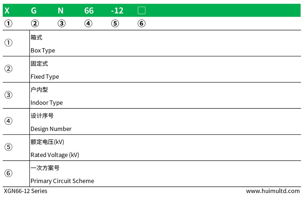
How to order
Feature
Structural features
● The switchgear is a cubical fixed structure, and the cabinet body is welded by thin plates and angle steel;
● The upper part of the rear of the switchgear is the main busbar room, and the top of the room is equipped with a pressure release device;
● The upper part of the front of the switchgear is the relay room, the small bus bar can be connected from the bottom of the room with a cable;
● The vacuum circuit breaker is installed in the middle of the switchgear, and a grounding switch or an outgoing side isolating switch is installed in the lower part;
● Current transformers, voltage transformers, and lightning arresters are installed in the rear of the switchgear. The primary cables exit from the lower part of the rear of the cabinet;
● The grounding bus is arranged at the bottom of the cabinet, which runs through the entire row of switch cabinets;
● The isolation switch and the grounding switch are operated on the left side of the front of the cabinet.
Work features
● The switchgear adopts the mechanical locking device, the locking structure is simple, easy to operate, safe and reliable;
● Only after the circuit breaker is actually disconnected, can the locking position be changed by the handle to prevent disconnecting the isolation switch with load;
● When the circuit breaker and the upper and lower isolation switch are in the closed state, and the handle is in the "working" position, the front cabinet door cannot be opened to prevent people from entering the live compartment by mistake;
● When the circuit breaker and the upper and lower isolation switches are in the closed state, the handle cannot be turned to the "overhaul" or "breaking" position to avoid accidentally breaking the circuit breaker. When the handle is in the "breaking" position, it can only break the upper and lower isolation switch, and cannot close the circuit breaker to avoid accidental closing of the circuit breaker;
● When the upper and lower isolation is closed, the grounding switch cannot be closed, and the handle cannot be turned from the "break" position to the "overhaul" position, which can avoid operating the live ground wire.
Application environment
● Ambient temperature: -15℃~+40℃;
● Altitude: ≤1000m;
● Relative humidity: daily average ≤95%, monthly average ≤90%;
● Seismic fortification intensity: Ⅷ;
● Installation site: no severe vibration and impact, and no fire, chemical corrosion, explosion and other dangers.
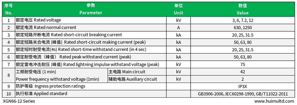
Technical data-sheet
Appearance and mounting dimensions
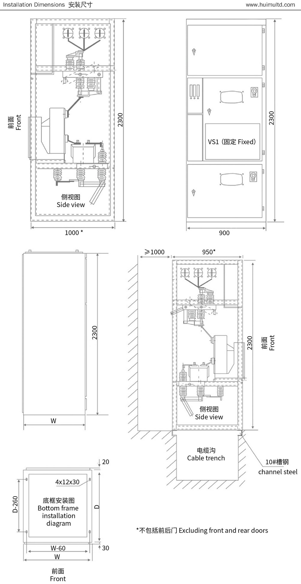
Installation process:
● The foundation channel steel protrudes 1-3mm from the ground, the unevenness should not exceed 1.5mm (within each meter), and should not exceed 5mm (within the full range);
● Place the switchgear on the foundation in order and adjust the installation position. Then fix it with M12 bolts or spot welding, and use M8 bolts to tighten between the cabinet and the cabinet;
● After disassembling the cover to install the main bus and primary cable, the contact surface of the terminal should be cleaned and coated with neutral petroleum jelly. After installation, pay attention to plugging the primary cable hole;
● Connect the grounding bus between the cabinets so that they are integrated along the arrangement direction of the switch cabinets. Check whether the grounding is lacking, whether the grounding loop is continuously conducted, and the grounding resistance is not more than 1Ω;
● Install the secondary cable. The cable is introduced from the bottom of the front of the cabinet, enters the relay room along the side wall, and is tapped on the terminal block; after installation, the cable hole is blocked;
● Clean the dust and sundries in the cabinet.
Get in touch with us now!
Please take a minute or two to complete this simple form to get reply in 24 hours, thank you!
*Please check the trash box of your mailbox, if you do not receive our email.


