MNS Series
Low Voltage Draw-out Switch Cabinet

Introduction
MNS Series Low Voltage Draw-out Switch Cabinet is suitable for power systems with a voltage of 660V (50~60HZ), and is mainly used for power conversion, distribution and control of power distribution equipment. MNS series is a new type modular cabinet assembled by factory with standardized modules. MNS series are widely used in power plants, substations, petrochemicals, metallurgical steel rolling, transportation energy, light industrial textiles, mining enterprises, residential communities, high-rise buildings and other places.
How to order
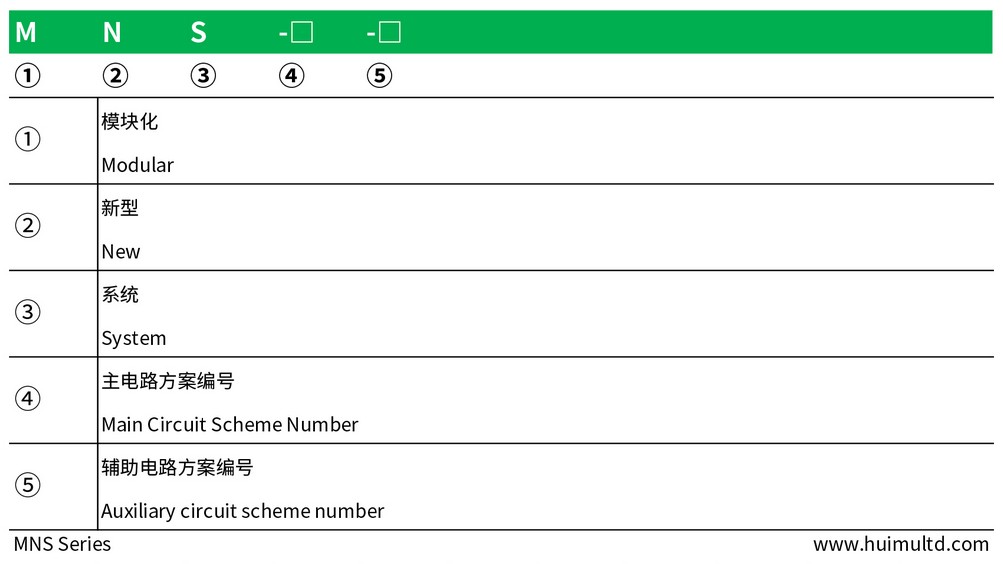
Classification:
● Power Distribution Center Cabinet (PC): Emax, MT, 3WN, AH, ME series circuit breakers can be used. ● Motor Control Center Cabinet (MCC): It is assembled by drawers of various sizes, and the main switch of each circuit adopts high-breaking plastic case circuit breaker or rotary load switch with fuse. ● Automatic Power Factor Compensation Cabinet (APFC) : with manual, automatic and remote power factor compensation devices.
Application environment
● Ambient temperature: -5℃~+40℃, the average value of 24h does not exceed +35℃;
● Altitude: ≤2000m;
● Relative humidity: monthly average ≤90% (the average temperature of the month is +25℃); relative humidity ≤50% (when the ambient temperature is +40℃). The relative humidity is related to the ambient temperature. The lower the ambient temperature, the higher the allowable relative humidity. For condensation caused by temperature changes, take appropriate protective measures (such as adding drainage holes);
● Transportation temperature: -25℃~+55℃, the average value of 24h does not exceed +70℃;
● Installation site: no severe impact, no serious pollution and chemical corrosion, no conductive dust or explosion hazard. Should prevent rain and moisture;
● When this device is used in offshore oil drilling platforms and nuclear power plants, a separate technical agreement should be signed.
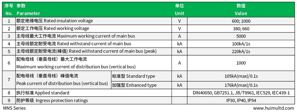
Technical data-sheet
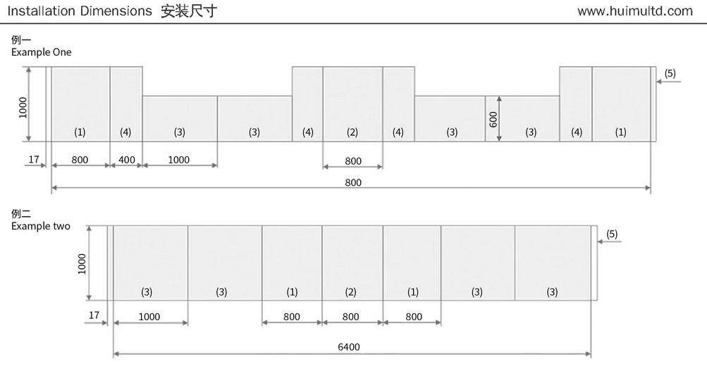
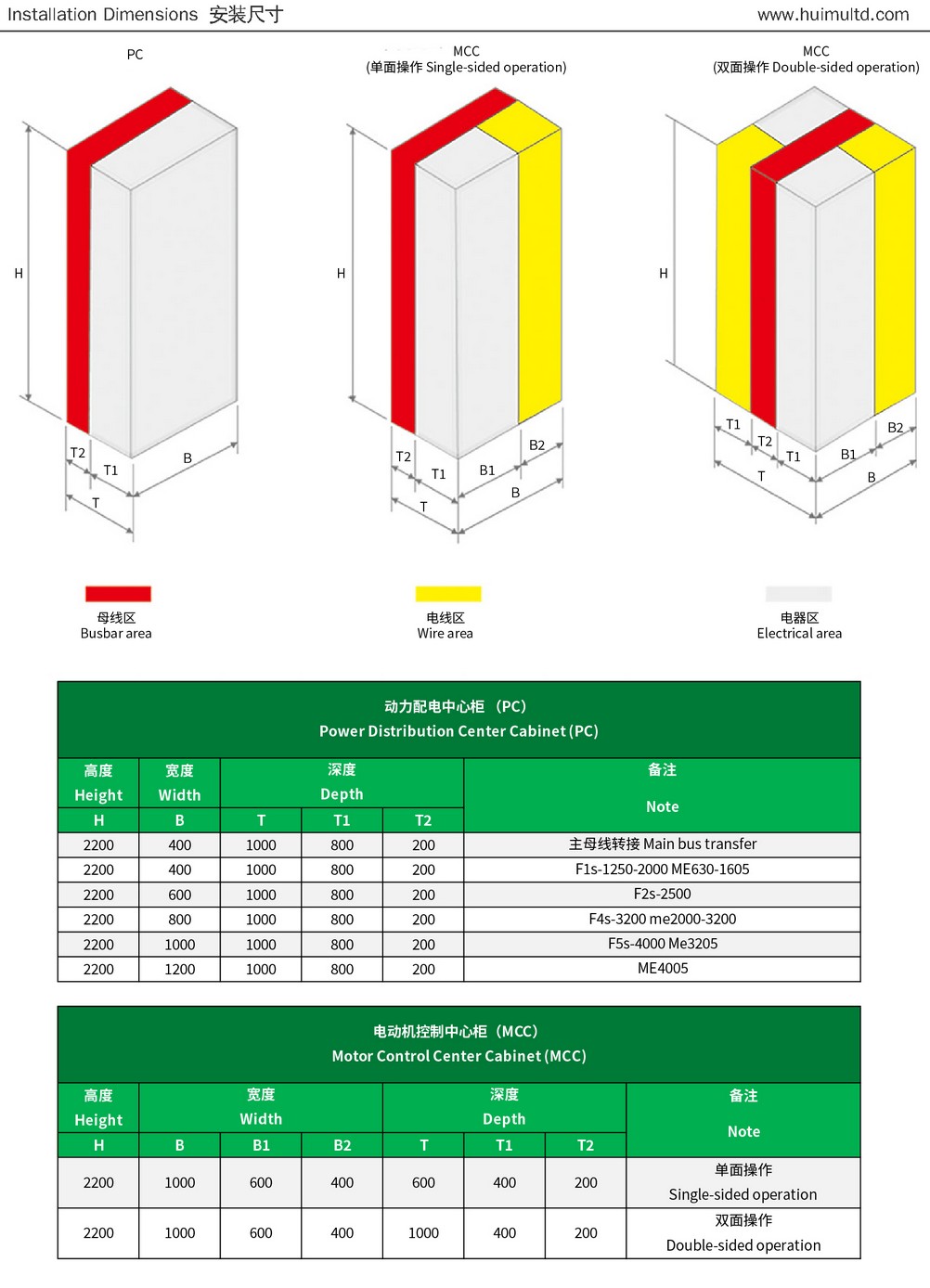
Appearance and mounting dimensions
Schematic diagram of combination method:
Installation diagram:
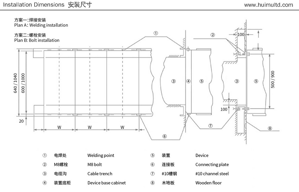
Schematic diagram of the cabinet:
Installation Precautions:
● The device is not allowed to tip over and subject to severe vibration.
● When the device is hoisted after unpacking, the transportation angle plate should be used, and the angle between the two steel wires should be ≤120°.
● If a forklift is used, no rollers or crowbars are allowed to operate directly on the bottom frame of the device.
● After the device is installed in place, if you want to move the position of the device a small distance, you can pry on the four corners of the test frame.
● Do not disassemble electrical products and parts at will in the device.
Get in touch with us now!
Please take a minute or two to complete this simple form to get reply in 24 hours, thank you!
*Please check the trash box of your mailbox, if you do not receive our email.


